|
How to Design & Build Ultra-Low Cost
Truss Structures
for the absolute
Minimum weight, Steel Usage, and Cost
1Spread out the "load
path" from the supports to the loads bear down.
Whenever
distributed loads have conventrated supports, then the supports must spread out
their support accordingly.
The following
illustration applies to applications for Flat-bed truck traiers (on the
right half) and for rail cars bodies (on the left side) with some
cross-over applications as noted.
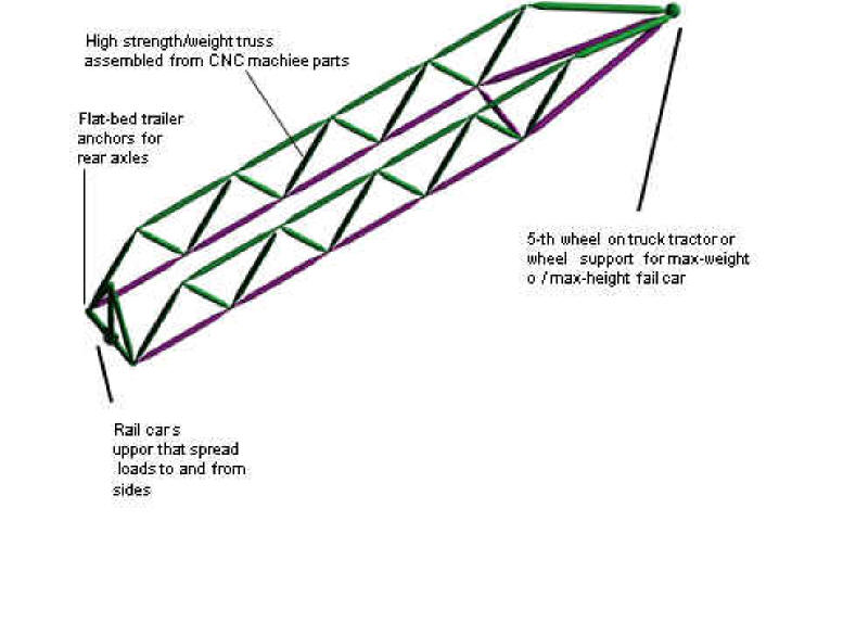
Trusses have alwaybeen the highest
strength/weight,
and now can be the lowest cost
The high strength per weight at low cost would be valuable
for:
Chasses for trucks, semi-tractors, farm
equipment, Earth-moving equipment, etc.
Chasses for racing cars and trucks, which has
been used since Maserati developed the “birdcage” space frame in the early
1960's. which consisted of 200 welded tubes that reinforces in high stress
areas! The techniques of this page need no welding, no reinforcing, and, with
more efficient layout may need up to five times fewer tubes because they follow load paths (as discussed below) so they cost so
much less that these design innovations could evolve into production
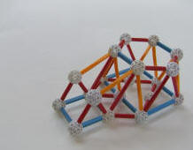
models. See Zometool model of a fully-triangulated frame for an
off-road racing truck with narrow engine
compartment on the left beside front wheels (not shown):
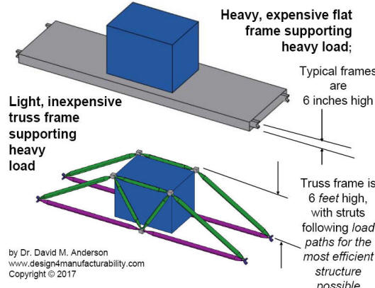
Long span structures that support heavy
loads, like railroad cars and locomotive chasses and elevated rail structures
(see first truss shape example below)
Light-weight structures that have to accelerate fast
as may be needed to move challenging masses fast.
Anchoring and concentrated loads in aerospace structures that benefit
from load-path analysis
Low-cost machine frames that can be backward
“drop-in” replacements for nard-to-build weldments: This is the focus on the
Steel Reduction Workshop.
OPTIMIZING DFM FOR
TRUSSES
How to optimize DFM for the highest strength per weight on the
lowest fabrication cost, material cost, and overhead cost:
For most of the opening opportunities listed above and more, the major .
strategies are the following DFM techniques
Automated CNC Fabrication
Design system architecture to be all fabricated on automated CNC machine
tools (milling machines, lates, swagging machines, etc) with pre-fab parts
rigidly and precisely by DFM techniques described below.
The triangles in trusses are these trusses
mostly have somewhat different shapces, which can be easily handled by Cellular
Manufacturing Cells using Mass
Customization principles; see
Cellular/Flexible
Manufacturing
DESIGNING THE OPTIMAL TRUSS
SHAPE
Synthesize the optimal truss shape in the following these examples from
simple planar truss to 3D space frames:
2D Planar
Truss: The Warren
Truss:
The three equilateral triangle Warren (zig-zag) truss has several times
strength per weight ratio than a flat beam because flat beam stresses
are always much higher near the center, whereas trusses can be designed so
that each strut has the same load and they are much lower, as shown in the
client example at the right.
A simple but higher version of this is the "King Post" truss, that
consists of two right-angle triangle. On the other hand, more
triangles in Warren truss would be lower but less efficient than catenary
trusses, (discussed below) which is the most efficient truss for
spans.
The Catenary Truss
A very efficient truss for supporting uniform loads is the "catenary truss.”
A catenary is the shape formed by a chain hanging between two level
points. Ancient builders would trace this shape and build masonry
domes and arches using this shape because the loads would transfer cleanly
along columns of blocks without needing any sideways stresses, This
catenaries are very efficient. Some of the machinery catenary trusses
presented below also have the catenary in compression and do not need
sideways bracing. Trusses with the catenary in tension can be designed
to have constant stress, thus being made in one piece.
Structurally,
the catenary truss is the ideal beam because the catenary shape matches
the load curve for beams that are supported at the ends, thus providing the
greatest strength for the least material, the lightest weight, and the lowest
cost. This type of truss is utilized in the most advanced bridges
The inverse of this is a suspension bridge in which the catenary
is a long cable with smaller cables connected to the bridge surface.
Catenary trusses, as shown below, can be utilized as cost-efficient frame work
that need to support weights (loads) over challenging distances, especially for
sub-frames that need to be light for accelerations. This may be the best design
approach for long beams like large machinery or frames for the lightest railroad
tracks.
Uniform
loadc atenary
Truss
with
constant-stress
lower"strap"

This truss will support a
uniform load, like on a floor or a road bed, and exert a constant stree on
the lower "strap" that supports the truss at each end.
Therefore, the strap can be the same thickness and be made of one piece of
metal or composite carbon fiber.
See Figure 16.4 from Chapter 16,
"Finding Efficient Forms for Trusses," from Design of Building Trusses,
by James Ambrose, Professor of Architecture, USC. 1994, John
Wiley & Sons.
Catenary
supporting
constant stress
"bridge" member

In
this truss, a true catenary arch member supports the a constant stress
"bridge" surface member, which can be made from a one piece of metal
of composite carbon fiber, which greatly simplifies construction. The
inverse of the catenary could be suspended from two towers, like the Golden
Gate Bridge. Note that no diagonal struts would be needed, which would
also simply machinery construction. See Figure 16.7 from the above
reference, in
Chapter 16, "Finding Efficient Forms for Trusses,"
Like all trusses discussed above, all the parts can be built automatically on
ordinary CNC machine tools. assembled by non-skilled labor, and retain
neat treatments or cold-rolled strength of the raw materials.
3D SPACE FRAMES
Space frames are three dimensional trusses that are fully triangulated and
can resust linear forces in all directions and resist torsion along all axes.
The simplest space frams is the tetrahedron which
can support a point load on three struts (like a camera on a tripod.
The Octahedron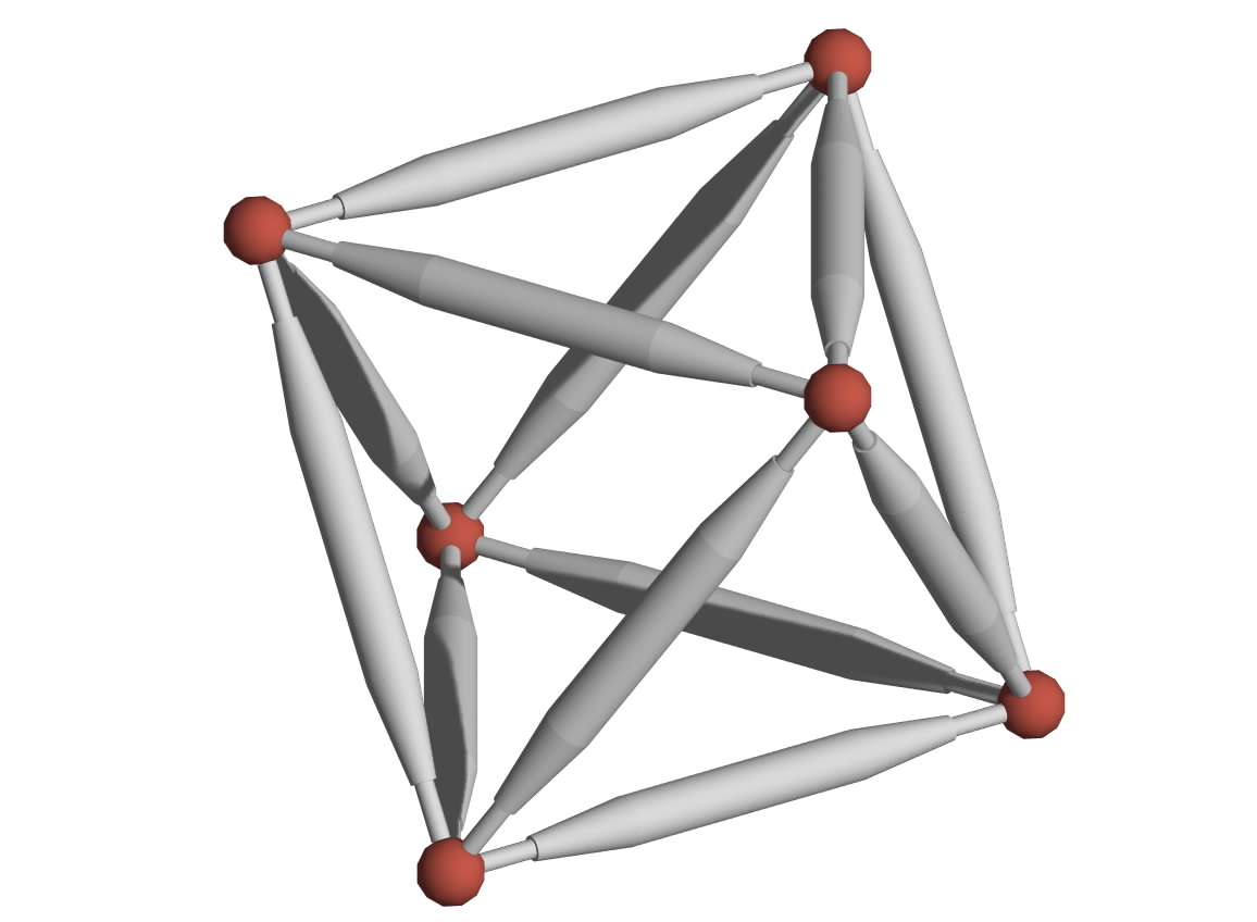
The Octahedron is a true space frame that
will support a solid object
on the top triangle while it and the truss is
supported on the bottom triangle.
MORE EXAMPLES
AND CONCEPTS
Truss Frame with Bearing Mounts for Shaft.
© 2018 by Dr. David M. Anderson.
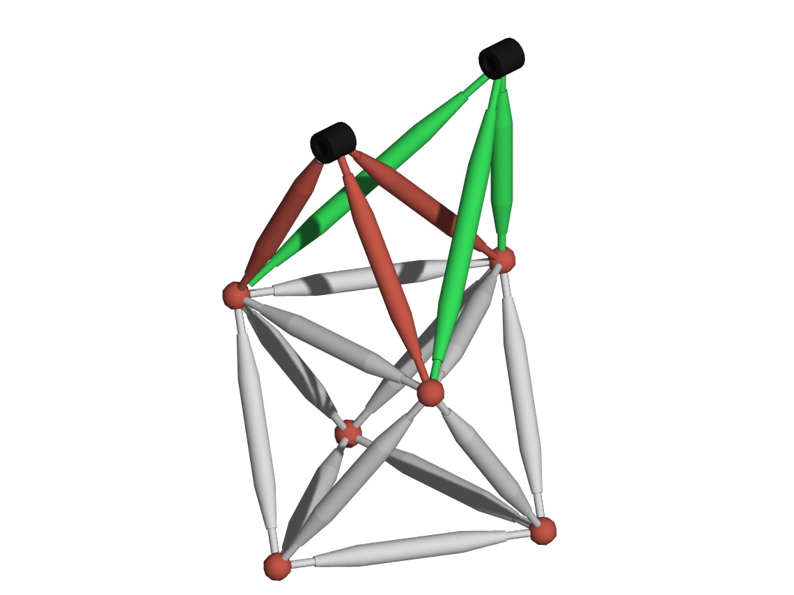
Two "tripods" can be bolted to any truss (in
this case, the above octahedron) to mount other structures like mount bearing
blocks to rigidly support machine shafts, axles, pivots, or any rotating
members. The bearing blocks have bearing mount surfaces bored and reamed
and also tapped holes on the outer surface on which to bolt the struts.
The tripod mounts result in fully triangulated
rigidity and is much stronger per weight than the usual techniques us using
heavy plates or weldments to mount bearings
If a single structural mount was needed, one tripod could be
utilized with an appropriate mounting surface.
Any subassembly could be bolted to any side
or multiple sides of any basic truss frame for functionality, for instance,
bearing blocks, in any plane.
The Strategy
The
strategy would be to
commercialize
proven parts with backwards compatible replacements with the same
functionality and strength (possibly enhanced) with much less total cost and
weight. This
would provide cost reduction now on existing products. This would also encourage
a leap-frog strategy where these low-cost parts could then become the
basis for new generation products.
The specific strategy to eliminate the abovementioned costs would be to
create an optimized concept/architecture for constant-stress trusses and
structures (which, by definition, use the least material) with the following
steps.
This strategy and approache are described
and justifies in theCost and steel
reduction workshop on its own page.n page.
The Approach
The approach would be based on the following premises:
Fabrication. All machined parts would be small enough to be set up
and made quickly on readily-available CNC machine tools in a single setup
(Guideline P14 in the
DFM book, which specifies that all operations should be
done in one setup on versatile CNC machine tools).
Welded
parts would be limited to those that are small enough to be machined after welding by the typical in-house machine tools. This
may be appropriate for bearing blocks and other junction parts if not feasible
to machine from a single block.
Assembly. Precise alignment of
these assembled pieces would be assured by the programmable part manufacture.
Mass Customized Tooling. Dr. Anderson has
written two books
on mass customization, and had experience designing flexible tooling as
Manager of Flexible Manufacturing at Intel's Systems Group and his own
Anderson Automation, Inc. Based on all this, his workshops show how to
design flexible processes that can programmably offer variety with less cost,
time, space, weight, and material usage.
The general principles of mass
customizing process design are summarized on the web article shows flexible processes for electronics
(Figure 1) and flexible processes for fabricated products (Figure 2) at
http://www.build-to-order-consulting.com/mc.htm . Another big
benefit of flexible tooling is that it enables spec changes or
customer-induced changes to be implemented faster than with inflexible
designs built in hard tooling, thus keeping them off the critical
path.
Steps for Reducing
Cost on Large Parts and Assemblies:
• Identify existing loads,
directions, and attachment points, which would then be graphically represented.
In a workshop setting, these could be projected from a active CAD screen or printed on several sheets of large paper
with dark lines for the next step.
• Brainstorm on various ways to
support these loads, with many ideas sketched on many printouts.
• Then
optimize the design of these parts for manufacturability and currently
engineered manufacturing strategies for trusses, assembling plates and bar
stock, and "space frames."
Trusses consist of struts
and nodes:
Struts. Purely tension members could be made of rods; compression struts
must be axisymmetric with the load path and wide enough to resist
buckling. This favors
tubing with threaded holes at the end to bolt to the node blocks. Very thick-wall
tubing could be plugged with threaded disks that could be joined to the tubing
with an automatically welded low-heat axisymmetric weld. For smaller thick-wall thickness, a clean,
inexpensive strut could be made by swagging down the ends to just past the tap
diameter for tapping threads that could then be bolted to the node blocks.
Swagged ubes are shown in the illustrations above (in grey), which can be inexpensively
procured from a swagging shop. In one application, a swaged tube cost
$40 for a 25 inch long tube, 2.5" OD, with an
1/8" wall that that included drilling-and-taping and facing off for a
precision length (wall thickness can go up to 1/4" and higher). The swagged struts can be made quite large
and strong, as was pursued in workshops for Caterpillar's underground coal
mining front loaders Finmechanica's
four-axle trailers and other workshops indicated by the blue hyperlinks
on the client page. In workshop exercises, Dr. Anderson leads a
company team to brainstorm on many concepts for struts-and-nodes to support all
the hardware in a frame or structure.
The nodes would have bolt holes for
the struts and all hardware that bolts to the structure.
Node
Blocks. Each node block would be designed and dimensioned so that
all operations for node attachment and and object mounting holes would be made in one setup (Guideline P14)
on an ordinary CNC machine tool. Families of similar parts could be
machined on
flexible fixtures that would be able to make all parts in the family
without setup delays and extra cost. The illustrations below show spherical
nodes (in red) for clarity. Actual nodes would each be milled out of bar
stock using various DFM design techniques to attach the struts and all the
hardware that needs to be supported. Dr.
Anderson helps companies design these through consulting after the
workshop and through remote consulting and design studies.
Workshops. Many
customized workshops have been conducted by Dr.
Anderson
This one-day workshop will apply unique DFM principle to
large parts for half the cost or better and significantly less steel
consumption.
This is the most effective way to reduce cost on existing products
because it focuses the most effective half-cost DFM principles on the least
manufacturable module in industrial machinery: structures and frames, which
usually are hogged out of large blocks or are welded and then go to
straightening, grinding, and drilling on mega-machines (see cost savings
summarized below).
The workshop will show a small group of your people how to quickly design
backward-compatible replacements that can “drop in” to existing product designs
for significant near-term cost savings without needing a full product
development cycle.
Workshop Format
The group would explore some of the most promising
opportunities in the workshop to the point where they look feasible and it is
clear how to proceed at which point responsibility could be assigned to pursue
each opportunity.
The group would also identify future opportunities to
be explored later based on pre-workshop research that will have identified some
opportunities. Opportunities will be summarized and then the workshop group will
vote on them for a baseline prioritization of opportunities.
Pre-workshop company research
should also plot steel cost from the time current
products were designed and extrapolate price trends into the future.
Audience. Product development team with all designated and potential
members, with at least one person representing each function and one person
knowledgeable about each proposed candidate structure. The workshop would
benefit from close proximity to the physical structures being analyzed.
Prerequisite: When a DFM class is give, workshop
attendees should attend the two-day DFM seminar first.
For a stand-alone workshop, the prerequisite would be be familiarity with the
original part, its brackets, and everything that attaches to them, CAD skills,
and familiarity with the parts welding process, and company or vendor machine
shop operations.
This workshop can be offered without the full DFM class if a
small team attends an upcoming webinar:
April
& Sept. webinars on Design for Lean
Manufacturing
2-day webinar:
April 19-22 and Sept 20-23 from 1-5 PM EST
Complete description at: https://qualitysupportgroup.com/design-for-lean-manufacturing/
Team
members can get a 15% discount is available (on request) 2 or more people from
the same company
Alternative: Consulting with company CAD
engineer.
An alternative would be ask Dr.
Anderson to do the above as a
design study
on a consulting basis, working with relevant company engineers and/or CAD
engineers. The
joint effort would present the most promising approaches for the company to
evaluate, select, and implement. Dr. Anderson is particularly effective for
complex parts that could benefit from more manufacturable design concepts and
concurrently engineered low-cost tooling and processing. He is in a unique
position to do machining/welding tradeoffs, since he once had his own machine
shop and has done welding since his college years.
He also has to-scale
CAD models for other layouts, like front and rear wheel loader frames, on
which he will work exclusive with the first mover to
contact him. Because of his
ethics code (from the Institute of Management Consultants) he will avoid
conflicts-of-interest by not working with direct competitors, so that means
first-come-first-serve for enlisting his considerable experience on these
techniques that he originated. See client engagements that included this
Steel/Cost Reduction workshop, as indicated by blue hyperlinks on his
clients page. For clients with new challenges,
he has a vast library of generic struts already drawn.
All of these
principles on DFM can be included in
your customized
class and workshop on DFM
or
the Most Effective
Product Development class
Here is an email you can use to send this
information around:
To: all
I just found a heavily-illustrated web page that shows
how to:
a) Design
very high strength/weight structures
that avoid the high cost, material use, and skill demands of
weldments and replace all that with automatically CNC- machined
parts that can be quickly assembled rigidly and precisely by the DFM
techniques described by the 50 articles on this site.
 `b)
Provide immediate cost and steel reduction
on existing products with backward-compatible "drop-in"
replacement structures which next-generation products
can be based on. `b)
Provide immediate cost and steel reduction
on existing products with backward-compatible "drop-in"
replacement structures which next-generation products
can be based on.
See www.design4manufacturability.com/low-cost-trusses.htm
new Article:
The Most Advanced Product Development Course
by the author of all 50 DFM
article in this site.
New Article: Strategy
If you want to discuss Trusses by phone ot
e-mail, fill out this form:
If your company makes any products
that have similar opportunities, contact Dr. Anderson for your own proposal for
workshops or design studies that will show you how greatly lower the cost of
your hardest-to-design parts. As a Certified Management Consultant (CMC),
Dr. Anderson's high ethical standards
prevent him from doing this for direct competitors, which means the first
to bring him in gets a unique competitive advantage.
To discuss this further, contact:
Dr. David M. Anderson, P.E.; CMC; Fellow, ASME
HalfCostProducts.com
www.design4manufacturability.com
www.build-to-order-consulting.com
1-805-924-0100;
anderson@build-to-order-consulting.com
[DFM Consulting] [DFM
Seminars]
[DFM Books] [Credentials]
[Clients] [Site Map]
[DFM article]
[Half Cost Products site] [Standardization
article] [Mass Customization article]
[BTO article] [Rationalization
article]
Copyright © 2022 by David M. Anderso1
|