New
subject on optimizing
plumbing for complex systems,
next section below:
How to design
high strength / weight structures
for greatly reduced weight, steel cosupt9ion,
cost, skill demands or mechanized tooling.
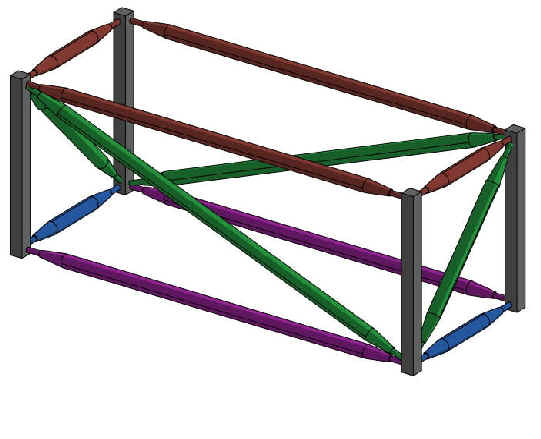
Case Study Example # 1: Low-Cost
Rectangular Machine
Frame

This low-cost
machine frame can be bolted together rigidly and precisely from parts
fabricated on ordinary CNC machine tools.
The nodes (at the
corners) would be CNC fabricated blocks through which bolts connect their struts
and mounts for all machinery components that need to be anchored in that area.
The outer edges of a
rectangle frame are made of machined rectangular tubing, to which covers or
doors could be easily attached to.
Interior components and
sub-frames would be supported by struts coming from the he main frame nodes
discussed below and triangulated to other existing nodes.
It is important to
realize
that such a frame can replace both the existing frame
AND all the
existing brackets to support components and sub-frames,
Trusses str omjrtrmy
stiff3
Warped weldments are the opposite
workshop topics to optimize wiring, plumbing. amd Upgrade-
ability.
The principles for both are presented in Section
3.1.12: Design Strategy for Electrical Systems and Sectiom 3.1.11 How to
Optimize All Design Strategies:
Options and upgrades can be made to be
easy to incorporate by adding, for instance to the framework: extra pre-drilled
mounting holes and surfaces; extra signal ports; extra power ports;
extra utility connections; extra utility capacity; and convenient mounting
spaces. These techniques will also allow you to cope with late customer
changes as discussed in section 2.8.
Doing this now will
add virtually no extra cost to the product, but
if you all you people work well together, the benefits will be enormous.
"Wiring
and cables are key elements of product
architecture and should not be left as an afterthought." Complete
electrical systems should be optimized at the concept / architecture level.
Cheers have gone up when this was said in a seminar
F or plumbing, one
proven technique can quickly show the opportunities in he
flowing exercises:
1. Project an image of the current plumbing
physical layout as a clear three-dimensional drawing,
photo, scale model, or actual hardware. The presenter should point out al the
complicating effects of locating the "crown jewels" first, and then
designing the frameworks and structural members, maybe somewhat arbitrarily. Plumbing
in complex systems tends to be routed "over ,under around and through"
alll of that ,usually in a octagonal grid, like plumbing in a house,
sometimes worse.
2. Project next to that, at the same scale, on the screen an an
"editable" image such as "solid mode" CAD image or pipe–layout
drawing tool, showing all the fittings, or even a free-hand drawing, showing the
theoretical minimum number of joints, for several scenarios.
Common examples of the elimination of joints;
Automobiles: For fuel and bake fluid, single
lines are programablly routed from the brake control to the brakes and from the
gas tank to the engine with no extra joints in between
Submarines: For long piping runs through
submarines, BAE engineers developed a programmable pipe bender that cam make
parts from a single length tube to fit into the tight spaces.
Then a multifuncti-functional team works together to optimize
the plumbing AND the framework AND the mounting of everything else.
esults:
Usually, the optimized scenario has about half the joints, although
it may look different and may have some installation or serviceability
challenges.
However the, the net result may be half the joints, this may be very
valuable and worth the effort, especially for fluids that are leak-prone in
situations where such leaks are hazardous, wasteful, inefficient, polluting,
or depleting fuel capacity. The smallest molecule – hydrogen -- can be all
of these.
Now that we the timely subjects of
wiring and plumbing optimized,
Back to the Assembled Frames
Eliminating problems of welding
This eliminates all the problems of welded
frames: skill demands, warpage, and post-weld machining on a mega-machine big
enough to machine all mounting holes into a warped frame. One ten foot
cube semiconductor fab machine frame has to do this
twice!
This site shows how to use these
principles to replace skill-intensive welding with
rigid
assembles of CNC machined parts as done in this workshop
as mentioned in all
the clients that con train hyper-links referring to this page.
STRATEGY
Replace high-skill labor welding (and high cost hogging out heavy
stock) with assemblies of parts that are automatically fabricated
on CNC machine tools and then assembled rigidly and
precisely by low-cost labor.
The parts can be built on
local CNC machine tools wherever the stell cost is lowest and assembled by
local low-cost labor. Or more specialized machine tools can make parts
which are then shipped in crates, not in bulky products!
Avoid the Problems, delays, and Costs Caused by Welding
The American Welding Society predicts a
welder
shortage of 400,000 by 2024.
Since
the average age of welders is
55, that means that
new
welds are not being trained!
Ask your HR or production
managers. One client said:
"You would not believe how hard it is
to find good welders in northern Minnesota!"
Fortunately, large or complex
weldments can be replaced by backward-compatible "drop-in: replacements
of assemblies of CNC - machined parts that are
assembled rigidly and precisely by DFM techniques, below.
Skill Demands
Welding requires skilled labor cost to make
consistently good welds plus other labor to position, fixture, clamp, straighten
warpage, and grind, and "touch up" (re-weld) as
necessary. Trying to reduce welder cost may raise all of these
other welder support costs, especially grinding, which is the first step
of rework of welding before re-welding.
Further , skilled labor shortages can reduce scalability and limit
ability to handle peak demand and growth
Loss of Strength
• Welding causes
loss of strength in the
"heat affected
zone" from welding and annealing, thus requiring more metal ato be neede if the welding weakens the raw material's
"cold-rolled" strength or heat-treated strength or
hardness enhancement.
Residual Stresses
• Welding induces residual stresses. The choices:
worsen structural failure
modes or lower the payload or have to add more
metal for the same payload.
• Residual stresses may also cause warping after metal removal,
especially large amounts of metal removal.
• An expensive, slow way to try to deal with heat warpage and metal removal
warpage is to anneal all the raw materials or work-pieces before welding
or before machining, which may require a large furnace that will also have expensive hourly
charges, transportation and queuing delays, especially if different jobs
require time to change to different annealing temperatures. But, don’t
forget that annealing weakens all metals.
Copyright ©2022 by David M. Anderson
HOW TO DO this for Large Structures
Large structures, like antennas, solar reflectors, machine frames, or any
large structures can be challenging to build if they must be precise.
The design techniques presented on this page (and more formally on Section
9.6 of the 2020 DFM book) will result in
large structures that are not only precise, but also rigid, very low cost, have
low skill demands, and will ultimately be scalable
without shortages. As shown in the trade group cited below, skilled
welders are getting harder to recruit, especially in out-of- the-way locations.
The usual approach to this is welding, which can not do any of these very
well. Some weldments can be rigid, may too much so, which might induce stress
concentrations which may ultimately weaken the structure.
Precise assembly methodologies recommend designing strictures –
, or replacing large weldments – with precise assemblies made
automatically on ordinary CNC machine tools and assembled precisely with
variously DFM techniques and guidelines.
Most of workshops done on this (noted with blue hyper-links on the
client page) have been on replacing weldments with more
manufacturable backward-combative "drop in" replacements
retrofitted onto current product designs for major short-term savings without
needing a full product development cycle.
These design templates could also be leveraged to other similar current products
or used as a basis for any new designs or product families. This would also
encourage a leap-frog strategy where these low-cost parts couldthen become the
basis for new generation products or the approach could be applied to new
low-cost products
Replacements can easily be compared to precise assemblies, which is usually
worth the effort. Of course new designs can, and should, start with this
approach – just learn the welding shortcomings for anyone who might ask
"why don’t you . . . " questions.
Generic Examples
Although most of the generic examples on this page replace
welded orthogonal frames,
Dr. Anderson has also created 3D models to replace welded sheet-metal frames,
large welded gimbals, channels, and I-beams
He has also done workshops to replace frames made of welded plates, welded
tubes, and castings.
REPLACEMENT FRAMES FOR MACHINES AND
LARGE STRUCTURES
How to design low-cost
replacement frames for substantial cost savings now on existing products
and/or base next generation products on these low-cost parts..
Text and illustrations Copyright © 2019 by David M. Anderson
Case Study Example # 2: Low-Cost Machine
Frame to Support an Object or Machinery
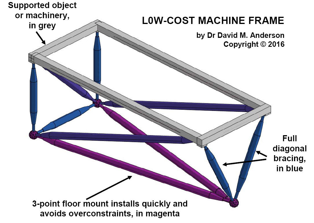
The low-cost machine frame concept shown bolts to
the existing framework of the supported object or machinery either directly
through adapter blocks, shown on each corner of the grey framework.
This truss is built as shown and
the trusswork is a fully triangulated space frame that mounts to the
floor on three points to install and align quickly and avoid the
overconstraints common in all four-point frame mounts. This truss
frame could be backward compatible with an existing four-point mounting
arrangement, with one new floor mount. If the supported object can be
supported by three mounts, then the frame would be the simpler
octahedron, as illustrated below in the comparison to a square welded frame.
For large trucks, there are so many weight saving
opportunities because the thickness of a channel frame is
determined by the loads around the bolt holes, but since the channel plate
must have constant thickness, most of this steel is "loafing" and thus much
heavier than necessary.
How to Design Structures for the
absolute
Minimum weight, Steel Usage, and Cost
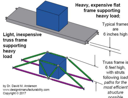
Spread out the "load
path" from the supports to the loads bearing down.
LOAD PATH STRATEGY FOR STRUCTURES OF LEAST WEIGHT AND
MATERIAL USAGE
This applies to all opportunities, but will be discussed in the context of the pair of drawings
below In the
simplified truss beam example shown in the lower illustration, the
colored truss
struts follow the “load paths” for the most efficient structure possible,
resulting in the lowest weight, and cost, possible for a given load.
Detailed Description. Specifically, the approach would be to replace the usual heavy
welded frames with a three-dimensional truss, consisting of
struts and nodes. Struts would be sized for their
specific tension / compression loads.
Development time can be quick because the struts cross-sections can be specified
thicker for prototypes and early evaluations with detailed stress analysis
following to reduce weight and material usage for production units.
A truss would provide the lightest
possible frame for a given strength because
its struts would align with all the load paths
between the loads themselves and their
supports on the floor.
The nodes would be placed at all of
these mounting locations and the struts
would connect them, even if they
are not co-planar. This would
eliminating all the separate brackets
now needed to do
this
Backward compatible "drop in" replacements
In all applications, the low-cost
truss frame replacement would be backward compatible and designed to "drop in"
to your current product, thus providing early cost, steel, and weight reduction now and then
the design work would become the foundation for next generation and fture
designs/
Because the
truss would follow the load paths, it would be the lightest possible structure
for a given strength, called a constant-stress structure with no excess
material that is 'loafing." To see this graphically, look at
the Finite Element Analysis (FEA) of your current designs. The
highest stress zones are usualy shown in red. These zones are
"constant stress" zones, which provide the highest streanth per
weight. By contrast, zones of lighter colors have less stress;
these are where the material is loafing.
Load-path trusses eliminate inefficiently utilized material and, thus, provide
the highest strength per weight.
THE WORKSHOP
Most of the workshops that Dr. Anderson has done were
for big structures with big loads, like the underground mining front-loaders for
Caterpillar, four-axle missile trailers for Italy's Finmeccanica’s DRS division
in the U.S., and many large machine frames, like the first two CAD models above.
Clients that held these workshops, or the consulting equivalent, are indicated
by blue hyperlinks to this page at the client list page.
tHE vALUD OF BACKWARD-COMPATIBLE REPLACEMENTS
Since the low-cost manufacturable replacements can be designed to be
back-ward compatible with expensive versions, this offers the following
leap-frog strategy:
-
It can providing near-term cost reduction without spending the
cost, resources, and calendar time for a new product development cycle.
-
The design can then becoming the basis for a next-generation development.
This one-day workshop applies very effective DFM principles to
large, heavy, or hard-to-build parts for major reduction in cost, material usage, and
build time. These improved designs could then be retrofitted onto current
products or used as a basis for new designs.
The workshop will show how to develop backward-compatible substitutes that will
replace expensive weldments, castings, or unnecessarily heavy machined parts with
more steel-efficient parts comprised of precise assemblies of CNC-machined parts that are rigidly
and precisely assembled by various DFM techniques.
Such a manufacturable structure could be based on assembled
plates or, for larger structures, look like the illustrations on this page, which will be
described below in the discussion of trusses that follow the load paths for the
highest strength per weight ratio.
Major Cost Reduction for Welded
Structures
Dr. Anderson is in a unique position
to facilitate workshop trade-offs between welding and machining, having owned
three welders and his own machine shop.
The most applicable large welded structures should be analyzed for
opportunities at the conceptual level with the goal of avoiding the following
costs:
-
high-skill labor cost to weld plus other labor to position,
fixture, straighten warpage, and grind. Skilled labor shortages raise
costs and can delay production and lower quality. Note that welding acute angles (e.g. in welded trusses or diagonal bracing) requires extra
skill to get enough heat between diverging members. For military and
mission-critical applications, these kind of welds require a special
certification.
• high steel usage and cost at a time when steel prices
are rising and will continue to rise for raw material and transportation
costs both for incoming materials and outgoing products.
• the
cost and delays for annealing the weldments
or the risk of fractures from residual stresses.
• the imprecise
and labor intensive practice of mounting parts in slots or large holes and
then aligning them manually, or
• machining large parts after welding, which may
require large, expensive machine tools and furnaces to anneal them, which:
• loss of strength in the heat affected zone from welding and
annealing, thus requiring more steel compared to steel used at its full
cold-rolled strength.
The Strategy
The
strategy would be to
commercialize
proven parts with backwards compatible replacements with the same
functionality and strength (possibly enhanced) with much less total cost and
weight. This
would provide cost reduction now on existing products. This would also encourage
a leap-frog strategy where these low-cost parts could then become the
basis for new generation products.
The specific strategy to eliminate the abovementioned costs would be to
create an optimized concept/architecture for constant-stress trusses and
structures (which, by definition, use the least material) with the following
steps.
The Approach
The approach would be based on the following premises:
Fabrication. All machined parts would be small enough to be set up
and made quickly on readily-available CNC machine tools in a single setup
(Guideline P14 in the
DFM book, which specifies that all operations should be
done in one setup on versatile CNC machine tools).
Welded
parts would be limited to those that are small enough to be machined after welding by the typical in-house machine tools. This
may be appropriate for bearing blocks and other junction parts if not feasible
to machine from a single block.
Assembly. Precise alignment of
these assembled pieces would be assured by the programmable part manufacture.
Mass Customized Tooling. Dr. Anderson has
written two books
on mass customization, and had experience designing flexible tooling as
Manager of Flexible Manufacturing at Intel's Systems Group and his own
Anderson Automation, Inc. Based on all this, his workshops show how to
design flexible processes that can programmably offer variety with less cost,
time, space, weight, and material usage.
The general principles of mass
customizing process design are summarized on the web article shows flexible processes for electronics
(Figure 1) and flexible processes for fabricated products (Figure 2) at
http://www.build-to-order-consulting.com/mc.htm . Another big
benefit of flexible tooling is that it enables spec changes or
customer-induced changes to be implemented faster than with inflexible
designs built in hard tooling, thus keeping them off the critical
path.
Steps for Reducing Cost on Large
Parts and Assemblies:
• Identify existing loads,
directions, and attachment points, which would then be graphically represented.
In a workshop setting, these could be projected from a active CAD screen or printed on several sheets of large paper
with dark lines for the next step.
• Brainstorm on various ways to
support these loads, with many ideas sketched on many printouts.
• Then
optimize the design of these parts for manufacturability and currently
engineered manufacturing strategies for trusses, assembling plates and bar
stock, and "space frames."
Trusses consist of struts and nodes:
Struts. Purely tension members could be made of rods; compression struts
must be axisymmetric with the load path and wide enough to resist
buckling. This favors
tubing with threaded holes at the end to bolt to the node blocks.
A clean,
inexpensive strut could be made by swagging down the ends to just past the tap
diameter for tapping threads that could then be bolted to the node blocks.
Swagged tubes are shown in the illustration below (in grey), which can be inexpensively
procured from a swagging shop. In one application, a swaged tube cost $40
for a 25 inch long tube, 2.5" OD, with an 1/8" wall that that included
drilling-and-taping and facing off for a precision length (wall thickness can go
up to 1/4" and higher).
The nodes would have bolt holes for
the struts and all hardware that bolts to the structure.
Node Blocks. Each node block would be designed and dimensioned so that
all operations for node attachment and and object mounting holes would be made in one setup (Guideline P14)
on an ordinary CNC machine tool.
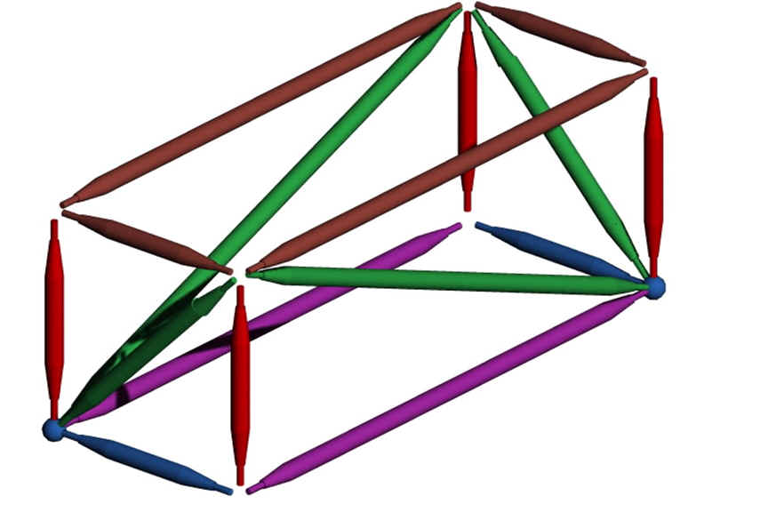
Rectangular truss with two spheres at nodes
Dr.
Anderson helps companies lay out the strut center-lines and bolt hole
centers through consulting, working
with the client's top CAD engineer on a frame, who first lays out the
attachment mounting geometries. These would be either small brackets or
a small washer that represents a larger sub-assembly bole
mount. That CAD engineer would project this to the team at the
second workshop afternoon meeting/
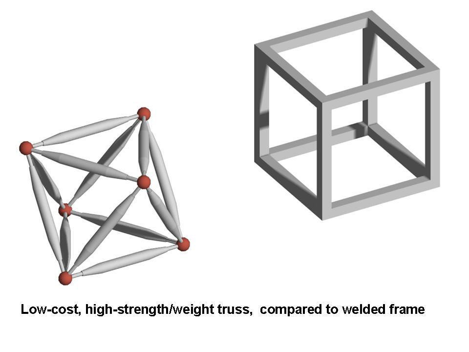
Comparisons with welded frames. The usual orthogonal
welded frame (like the one on the right) needs much skilled labor to weld, which
results in a warped structure that must have holes drilled after welding
on an expensive mega-machine used for large structures. Plus all 8 corners
would have to be ground for appearance or sanitation. And this is
without
diagonal bracing, which would require 6 more braces and 12 more welds, all of
which will induce residual stresses that will reduce the load capacity or
require more material.
By contrast, the octahedron truss (on the left) has all
parts machined automatically on ordinary CNC machine tools. The
struts are assembled to 6 nodes precisely and rigidly by unskilled labor.
The simplest truss, the octahedron, is shown, although trusses can be
designed to any shape, like existing
rectangular frames, as shown above.
For mounting loads, orthogonal frames, like
the one shown on the right, usually need many extra brackets to attach hardware
to the frame.
With trusses, the nodes also
serve as
all the mounts for all the mounted hardware, since all the struts and
nodes can be uniquely fabricated (this is called
mass customization) so
that a node is next to every
hardware mount. Trusses have inherent diagonal bracing and can support loads
without any warpage, overconstraints, or residual stresses.
Case Study # 3 Example: Commercial vehicle frames. These
principles could apply to "work vehicles" whose frames have to support heavy
loads, like engine/transmission units for work trucks, engine/generator units
for locomotives or portable power plants, buckets or dump bodies for
earth-moving equipment, combines, engines for farm equipment, or the loads for
heavy-haul trucks or trailers.
The illustration compares the typical heavy, expensive flat frames with light,
inexpensive truss framework: The typical flat frames (shown on top) may be
supported by I-Beams or channels (in the case of Semi-trucks) that would
have to be very heavy to support heavy loads in the middle of long
frames, especially if they were only a few inches high. Welded frames
could be thicker, but at a high cost for steel and skilled labor; for instance,
one wheel-loader frame is made from 300 pieces welded together to form
the two pivoting frames (a 3D CAD model of a low-cost replacement is available
on request).
Case Study #4 example: Low-cost Backhoe Boom
Replacement for Weldment
The low-cost assembly (upper CAD model) replaces the heavy welded boom (lower
photo)
The assembled replacement is a truss, which is the lightest structure for
a needed strength, so it uses a fraction of the steel, and material cost,
compared to a structure made of heavy plate. The truss is built automatically on
ordinary CNC machine tools and assembled by non-skilled labor. Note that the heavy load exerted by the boom piston is connected
to the thick "elbow" structure with the load supported at the ends of two
tetrahedrons. This CAD model and more machine frames below were drawn
by Dr. David M. Anderson, copyright © 2018. He
also has to-scale CAD models for other layouts, like front and rear wheel
loader frames, which he will work exclusive with the first mover to
contact him
The conventional design in the photo is made by welding many large heavy plates,
which has high skill demands and weakens the steel in the heat-affected-zone.
In order to provide accurate mounting holes and surfaces, which is essential for
industrial machinery frames, the warped weldment must be machined on an
expensive mega-machine with very high hourly costs for positioning,
machining, repositioning, and inspections, not to mention transportation and
queuing delays.
MORE EXAMPLES AND CONCEPTS
Truss Frame with Bearing Mounts for Shaft.
© 2018 by Dr. David M. Anderson.
Two "tripods" can be bolted to any truss (in
this case, the above octahedron) to mount other structures like mount bearing
blocks to rigidly support machine shafts, axles, pivots, or any rotating
members. The bearing blocks have bearing mount surfaces bored and reamed
and also tapped holes on the outer surface on which to bolt the struts.
The tripod mounts result in fully triangulated
rigidity and is much stronger per weight than the usual techniques us using
heavy plates or weldments to mount bearings
If a single structural mount was needed, one tripod could be
utilized with an appropriate mounting surface.
Any subassembly could be bolted to any side
or multiple sides of any basic truss frame for functionality, for instance,
bearing blocks, in any plane.
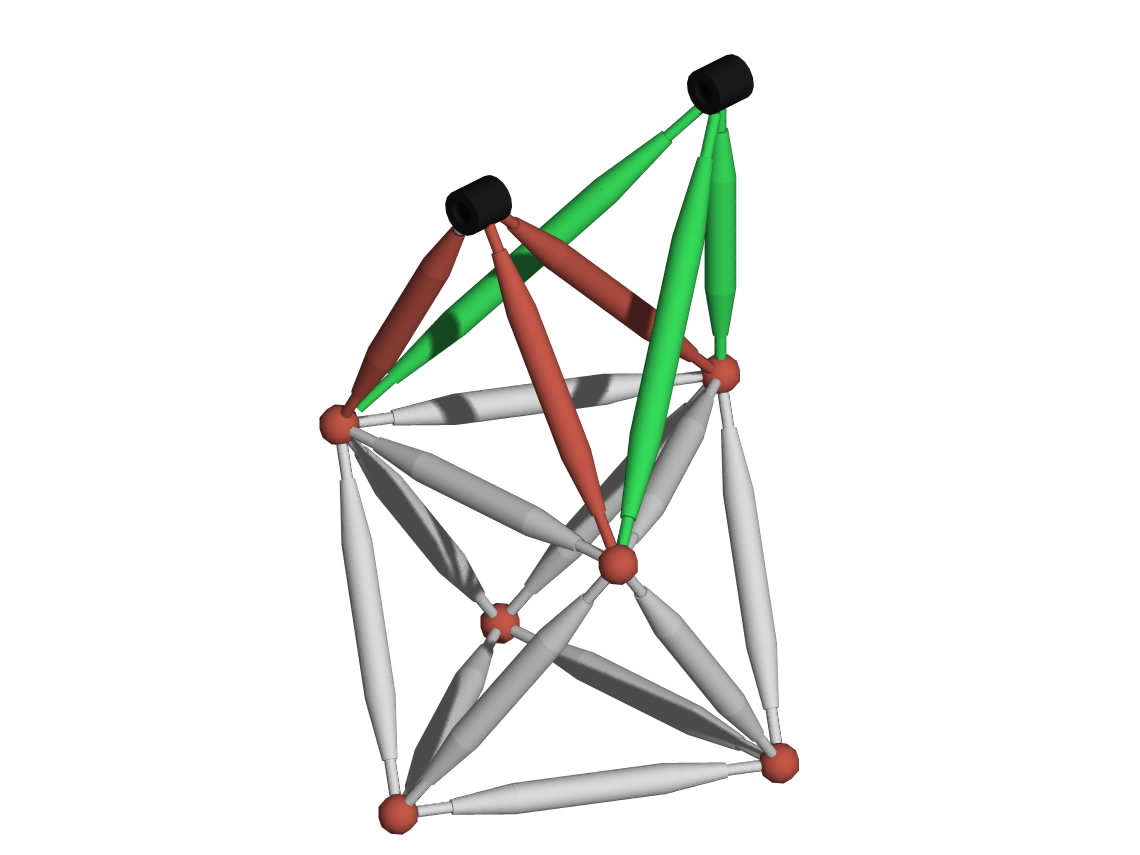
The Catenary Truss. Structurally,
the catenary truss is the ideal beam because the catenary shape matches
the load curve for beams that are supported at the ends, thus providing the
greatest strength for the least material, the lightest weight, and the lowest
cost. This type of truss is utilized in the most advanced bridges
The inverse of this is a suspension bridge in which the catenary
is a long cable with smaller cables connected to the bridge surface.
Catenary trusses, as shown below, can be utilized as cost-efficient frame work
that need to support weights (loads) over challenging distances, especially for
sub-frames that need to be light for accelerations. This may be the best design
approach for long beams like large machinery or frames for the lightest railroad
tracks.
Like all trusses discussed above, all the parts can be built automatically on
ordinary CNC machine tools. assembled by non-skilled labor, and retain
neat treatments or cold-rolled strength of the raw materials.
This illustration shows a physical model, which can produce many ideas
quickly and can be passed around in meetings.. These model parts are made
by ZomeTool, which was designed by PhD mathematicians for molecular
biologists and structural engineers in addition to being widely available as
toys (see
http://www.zometool.com/science/ ).
In this model, the red spheres (like in the above CAD models) represent the nodes that
connect the struts and are also the mounting blocks for objects. The black
spheres support the ends of the beam and anchor it.
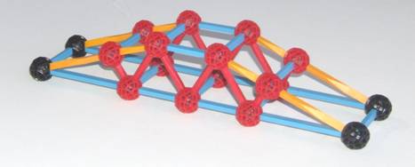
Next Example: The Zig-Zag Truss for Long Structures. Similar
techniques can be used to create a
"zig-zag (Warren) truss for booms, masts or
long structures.
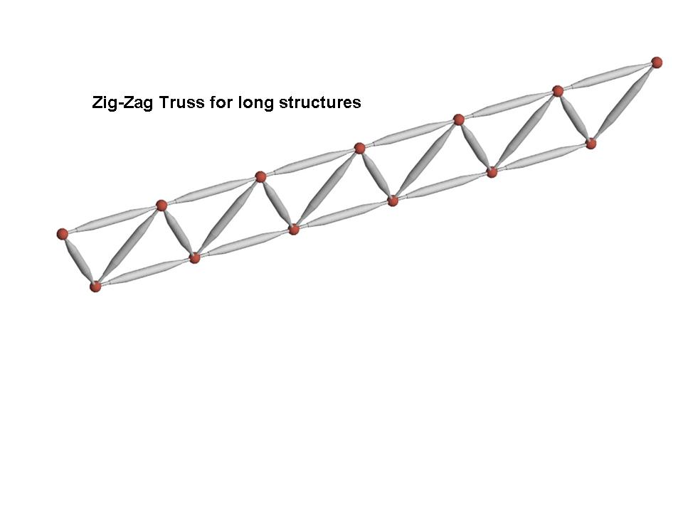 Additional truss members in a perpendicular plane can provide
lateral stiffness. Similarly, three strut columns could provide lateral and torsional stiffness. These will be the lightest and strongest structures
possible without the cost, excess steel, and difficult machining of long
channels/bar-stock and without the warpage, distortion, imprecise hole
locations, and skill demands of welded trusses.
The Results
The results would
be much lower cost from:
• quick machining on readily-available CNC machine tools
• quick
setup concurrently engineered for whole part families to
further reduce machine time
• quick assembly with accuracy assured by
programmably machined features
• higher strength per weight (meaning
higher strength per material cost) because of:
• more structurally efficient designs (lower stresses to
support a given applied load)
• all material would remain at
cold-rolled strength and heat-treated strengths could be preserved
These truss structures
would provide the absolute lowest weight for a needed strength.
Cost
Reduction for
Large
Machined Parts
For fabricated parts now made of excessively thick steel, the workshop group
would start by identifying the loads and load paths. Then we conceive of
structural shapes that match the load paths, which will probably not be a constant
cross-section slab that has a lot of under-stressed material that leads to
unnecessary cost and weight. Then we brainstorm on optimal assemblies of
CNC-machined parts whose cross-sections are matched to the load, thus
approaching constant-stress parts, which have the highest strength per
weight. This would be accurately and rigidly assembled by various DFM techniques
in which the precision is entirely determined automatically by the CNC machines.
These techniques include DFM
Guideline A3, in which mating parts would be aligned to sub-mill
tolerances by inexpensive pairs of round and diamond dowel pins in reamed
holes. Parts could be designed to be self-fixturing or simple fixtures could
be concurrently engineered to hold parts during alignment and clamping together
for fastening. Aligned parts would
then be bolted/riveted together with appropriate bolt strength, torque settings,
and retention strategies.
Cost
Reduction for Large Cast Parts
Cast parts require expensive tooling and lengthy and costly setups, which
usual force the OEM to order a large batch to amortize the setup costs,
but this violates lean production principles and makes it hard to do build to
order (see
http://www.build-to-order-consulting.com/sbto.htm). For
large or complex castings, there may be a limited supplier base who can cast
them, thus increasing transportation costs, shipping delays, and possibly queues
for busy suppliers. For example, for a certain size of large Diesel engine
blocks, there are only two suppliers in the world who can make them.
Further, castings all require machining, which may require an expensive
mega-machines for large castings, which may also incur lengthy setups,
queues, and delays to ship large castings to shops with mega-machines.
The workshop group
would start by identifying the loads and load paths. Then we conceive of
structural shapes that match the load paths. Then we brainstorm on optimal
assemblies of CNC-machined plates whose cross-sections are matched to the load, thus
approaching constant-stress parts, which have the highest strength per
weight. This would be accurately and rigidly assembled by various DFM techniques,
like Guideline A3 mentioned above.
The above techniques could replace many
hard-to-make large parts and fasten multi-part assemblies.
Workshop
This one-day workshop will apply unique DFM principle to
large parts for half the cost or better and significantly less steel
consumption.
This is the most effective way to reduce cost on existing products
because it focuses the most effective half-cost DFM principles on the least
manufacturable module in industrial machinery: structures and frames, which
usually are hogged out of large blocks or are welded and then go to
straightening, grinding, and drilling on mega-machines (see cost savings
summarized below).
The workshop will show a small group of your people how to quickly design
backward-compatible replacements that can “drop in” to existing product designs
for significant near-term cost savings without needing a full product
development cycle.
orkshop Format
The group would explore some of the most promising
opportunities in the workshop to the point where they look feasible and it is
clear how to proceed at which point responsibility could be assigned to pursue
each opportunity.
The group would also identify future opportunities to
be explored later based on pre-workshop research that will have identified some
opportunities. Opportunities will be summarized and then the workshop group will
vote on them for a baseline prioritization of opportunities.
Pre-workshop company research
should also plot steel cost from the time current
products were designed and extrapolate price trends into the future.
Audience. Product development team with all designated and potential
members, with at least one person representing each function and one person
knowledgeable about each proposed candidate structure. The workshop would
benefit from close proximity to the physical structures being analyzed.
Prerequisite: When a DFM class is give, workshop attendees should attend the
two-day DFM seminar first. For a
stand-alone workshop, the prerequisite would be be familiarity with the original
part, its brackets, and everything that attaches to them, CAD skills, and
familiarity with the parts welding process, and company or vendor machine shop
operations.
Faster, lower-cost alternative: Hourly
Consulting with company CAD engineer(s).
An alternative would be ask Dr.
Anderson to do the above as hourly consulting (billed
in 10 minute increments with no minimum) working with relevant company engineers and/or
a CAD engineer(s). The
joint effort would quickly present the most promising approaches for the company to
evaluate, select, and implement.
Dr. Anderson is particularly effective for
complex frames or structures that could benefit from more manufacturable design concepts and
concurrently engineered low-cost fixtures (at http://www.build-to-order-consulting.com/flex-mfg.htm
) and processing. He is in a unique
position to do machining / welding tradeoffs, since he once had his own machine
shop and learned how to use three welders.
He also has to-scale
CAD models for other layouts, like front and rear wheel loader frames, on
which he will work exclusive with the first mover to
contact him.
Because of his
ethics code (from the Institute of Management Consultants) he will avoid
conflicts-of-interest by not working with direct competitors, so that means
first-come-first-serve for enlisting his considerable experience on these
techniques that he originated.
See client engagements that included this
Steel/Cost Reduction workshop,
as indicated by blue hyperlinks on his
clients page.
For clients with new challenges,
he has a vast library of generic struts already drawn.
Workshops Done and Proposed:
Dr. Anderson has already done workshops for low-cost
frames for: underground coal mining vehicles; four-axle trailers for heavy
loads; large paper converting machinery; 12' high box-makers; dock-scale natural
gas compressors; fuel-cell back generator port block; framework for large ASRS
warehouse; low-cost joints in a 400' long window glass vacuum chamber; cabinetry
strategy to accept off-the-shelf enclosure modules; and nuclear plant worst-case scenario filters.
Dr. Anderson has personally done both
welding and owned his own machine shop, and, thus, is a good position to advise
on tradeoffs between welding and machining. See sixth paragraph of his
credentials page.
He has proposed this workshop or consulting
studies for:
-
Many low-cost frame and structures for industrial machinery
(like CAD model above)
-
Molding machinery foundations (CAD model available)
-
Large medical equipment gimbals (CAD model available)
-
Semi-truck chasses
-
Very large dump-trucks chasses
-
Wheel-loader (wheeled front loader) (CAD model available)
-
framework for farm machinery
-
Mobile distributed) power plant chasses
-
Diesel engine blocks (concept sketch available)
-
Long-span structures that support heavy loads, like railroad
cars and locomotive chasses (physical model available)
-
Light-weight long-span structures for high-speed motion
(physical model available)
-
Lighter weight airplane structures to support concentrated
loads like engines and landing-gear.
If your company makes any products
that have similar opportunities, contact Dr. Anderson for your own proposal for
workshops or design studies that will show you how greatly lower the cost of
your hardest-to-design parts. As a Certified Management Consultant (CMC),
Dr. Anderson's high ethical standards
prevent him from doing this for direct competitors, which means the first
to bring him in gets a unique competitive advantage.
All of these
principles on DFM can be included in
your customized
class and workshop on DFM
or
the
Most Effective
uct Development class
Here is an email you can use to send this
information around:
To: all
I just found a heavily-illustrated web page that
shows how to:
a)
Design ultra-low-cost frames
that avoid the high cost, material use, and skill demands of
welded frames and replace all that with automatically CNC-
machined parts that can be quickly assembled rigidly and precisely
by the DFM techniques described by the 50 articles on this site.
 `b)
Provide immediate cost and steel reduction
on existing products with backward-compatible
"drop-in" replacement frames which next-generation products
can be based on. `b)
Provide immediate cost and steel reduction
on existing products with backward-compatible
"drop-in" replacement frames which next-generation products
can be based on.
See
www.design4manufacturability.com/steel-reduction-workshop.htm
The very first step may be to start with a few hours of
thought-leader
consulting
to help formulate strategies and implementation
planning.
To discuss this further, contact:
Dr. David M. Anderson, P.E.; CMC; Fellow, ASME
HalfCostProducts.com
www.design4manufacturability.com
www.build-to-order-consulting.com
1-805-924-0100;
anderson@build-to-order-consulting.com
[DFM Consulting] [DFM
Seminars]
[DFM Books] [Credentials]
[Clients] [Site Map]
[DFM article]
[Half Cost Products site] [Standardization
article] [Mass Customization article]
[BTO article] [Rationalization
article]
Copyright ©20224by David M. Anderson
|